Tekno RC EB410 Behind the Design
Part Two
In part two of our series, we go into greater detail and explain the logic behind some of the features of the new EB410.
Shaft-Drive and Differentials:
The first decision to be made was how to get power to the wheels. It was an easy decision for us to choose a shaft-drive system over a belt drive system due to the advantages in durability, efficiency, adjustability, and ease of maintenance. Belts can slip or strip under the load of modern brushless motor systems. The increased friction of belts versus shafts/gears wastes energy, reduces runtime, and hinders top speed. A shaft-drive system easily accommodates a center differential, which is critical for adjusting the front/rear power transfer characteristics. Finally, gaining quick access to all three differentials was one of our goals that could have only been met with a shaft-drive system.
On the topic of differentials, we knew it was going to be important to maximize the internal volume of the diff cases. Increased fluid capacity means the differentials can work more efficiently and consistently. We did not see the point of including a center differential and then basically locking it up with 200K or thicker fluid. With the volume maximized, the resulting tuning window is much larger and can be fine tuned like the differentials used on larger 1/8th scale vehicles.
Driveline:
When it comes to the driveline, achieving maximum efficiency and reducing wear are of utmost importance. Where other buggies may have a twelve degree or higher compound angle driving the front differential, the EB410 has less than one degree. This reduces friction and increases acceleration out of corners.
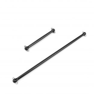
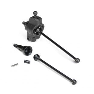
We opted for a bearing-captured CVA drive system to transfer power to the wheels. Aside from ensuring you will not lose a drive pin, it allows for larger inner wheel bearings that increase support and durability of the stub axles. The hefty 6mm diameter hardened steel stub axles are surprisingly lightweight due to extra machining operations. In addition, they make use of our existing hex options for the SCT410.3, allowing for different wheel offsets and track width adjustments. Despite the 6mm axle, we maintain the industry standard M4 wheel nut size ensuring replacement parts are easy to find. Center driveshafts are machined from 7075 aluminum and feature the same tapered design found on the EB48.4 1/8th scale buggy.
Reverse Bellcrank Steering System and Front Bulkhead:
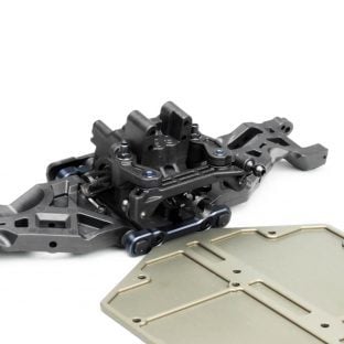
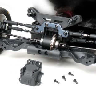
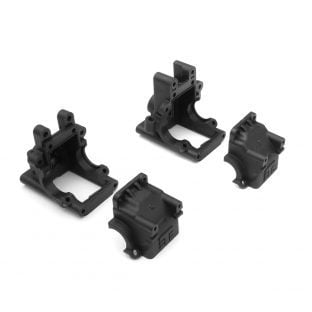
The EB410 incorporates the first reverse bellcrank system available for 4WD off-road 1/10th buggies. It is something 2WD buggies adopted years ago to help smooth out the steering response and improve consistency through the turns. This was no easy feat, but we achieved it by going all out on the front bulkhead design. It is the single most complex part of the EB410, and possibly of our entire history.
We had many goals to meet with the front bulkhead for us to move forward with the rest of the design. Goals such as quick access to the differentials, the ability to completely seal the gearboxes from the elements, a near straight input to reduce center drive angles, durability to survive hard crashes, and finally, a support structure for the entire steering system. The insanely complex mold was manufactured, tested, and fine tuned nearly a dozen times to meet the requirements we set forth. On the track, you will immediately notice how smooth and linear the steering is into and out of corners.
 |  |
CNC Machined Components:
Anyone familiar with our products knows we put a premium on how the chassis integrates with the rest of the components. We use aircraft-grade 7075 aluminum and high quality hardened steel alloys for all critical parts such as the chassis, hinge pin braces, motor mount, and driveline components.
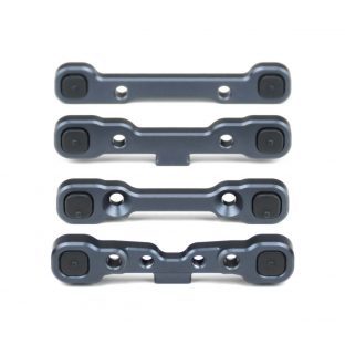
The fully machined chassis has been extensively milled out, not only to reduce weight but also to lower the center of gravity for everything installed in the vehicle. The battery, ESC, and RX all sit 1.5mm below the top surface of the chassis. The adjustable hinge pin brace system is a scaled down version of what you would find in our 1/8th scale line of vehicles. It is easy to adjust and tune, and just as durable as you would expect.
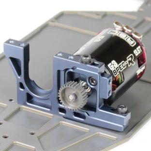
The two piece motor mount system makes gear mesh adjustment and motor removal an easy task. It was designed to produce the lowest center of gravity possible and allows easy access to the center differential without affecting the gear mesh. Lastly, chassis layout places the motor in a location that facilitates the cleanest wiring scheme of any 4WD on the market.
Shocks:
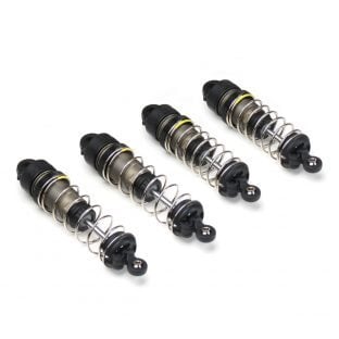
At 13mm, the EB410 shocks are truly big bore. Some might ask, “Why not go with a standard 12mm design?” Our goal was to create an extremely durable and reliable shock system and this meant using 3.5mm shock shafts. But we felt the larger shaft diameter displaced too much oil volume in relation to a 12mm shock body. So in an effort to produce the most consistent shock unit and maintain a high oil capacity, we decided that a 13mm shock body would be best.
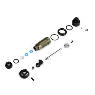
Another 30-year-old throwback that still exists in 1/10th scale offroad is the use of E-Clips to secure shock pistons. Not only is this old technology, it also makes changing pistons and working on shocks an unfriendly affair. We did away with this ancient practice by designing a piston and shaft that tightly integrate together. A custom low profile screw secures the assembly and maximizes stroke length.
A locking spring perch design first seen on our 1/8th scale vehicles makes an appearance on the new buggy. This means your springs will stay firmly seated and in action at all times. An extremely compact shock cartridge combined with low profile shock caps provide class-leading suspension travel while simultaneously making use of shorter shock towers for a lower center of gravity. This enables the EB410 to glide over large bumps and land jumps with complete control.
We felt it necessary to include an easier way to adjust droop on a 1/10th scale vehicle. Droop is an important adjustment that affects how the buggy handles. Until now, you had to either screw or unscrew the shock rod end, or worse, take apart the entire shock to add or remove internal limiters. Racers often look for easier adjustments to make rather than go through this rigamarole, even though adjusting droop may yield the most significant improvements on the track. We accomplished this with the simple addition of droop pads on the chassis and droop screws on the arms.
What’s Next?
Thanks for reading. In the next article we will unveil the exclusive chassis layout in detail. Stay tuned!
